What is GPIO?
GPIO stands for General Purpose Input Output.
The Raspberry Pi has two rows of GPIO pins, which are connections between the Raspberry Pi, and the real world.
Output pins are like switches that the Raspberry Pi can turn on or off (like turning on/off a LED light). But it can also send a signal to another device.
Input pins are like switches that you can turn on or off from the outside world (like a on/off light switch). But it can also be a data from a sensor, or a signal from another device.
That means that you can interact with the real world, and control devices and electronics using the Raspberry PI and its GPIO pins!
Taking a Closer Look at the GPIO Pins
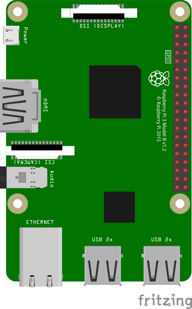
This is an illustration of the Raspberry Pi 3.
The GPIO pins are the small red squares in two rows on the right side of the Raspberry Pi, on the actual Raspberry Pi they are small metal pins.
The Raspberry Pi 3 has 26 GPIO pins, the rest of the pins are power, ground or "other".
The pin placements correspond with the table below.
Taking a Closer Look at the Breadboard
A breadboard is used for prototyping electronics, it allows you to create circuits without soldering. It is basically a plastic board, with a grid of tie-points (holes). Inside the board there are metal strips connecting the different tie-points in specific ways.
In the illustration below we have highlighted some of the sections with different colors. This is to show you how the grid is connected.
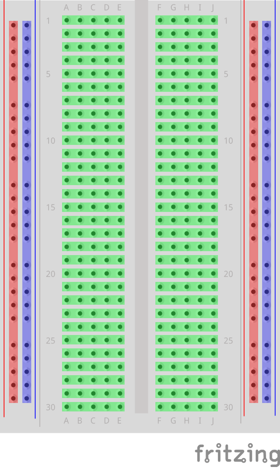
The different sections of the breadboard:
- On the left, and right, side there are 2 columns of tie-points. All the tie points in each of these columns are connected.
- The Power Bus - The columns highlighted with red. There are usually used to connect power to the Breadboard. Since the entire column is connected, you can connect power to any of the tie-points in the column.
- The Ground Bus - The columns highlighted with blue. There are usually used to connect Ground to the Breadboard. Since the entire column is connected, you can connect ground to any of the tie-points in the column.
- Rows of connected Tie-Points - The rows highlighted with green. The tie-points of each of these rows are connected, but not the entire row! The left side tie-points are connected (A-B-C-D-E), and the right side tie-points are connected (F-G-H-I-J).
- In the center of the Breadboard there is a Trench, this separates the left and right rows. The width of the trench is designed so that many Integrated Circuits fit across it.
Install the onoff Module
To interface with the GPIO on the Raspberry Pi using Node.js, we will use a Module called "onoff".
Install the onoff module using npm:
pi@w3demopi:~ $ npm install onoff
Now onoff should be installed and we can interact with the GPIO of the Raspberry Pi.